2.1.2
High Capacity bodies can be specified for Standard Square or Large Rectangular caps and must be specified to accommodate an unsealed or sealed cap installation.
| Unsealed (Type V) | Sealed (Type VI) | |
|
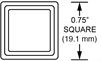
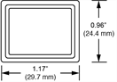
Standard Square
|
|
|
|
|
|
|
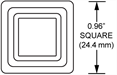
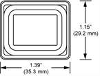
Large Rectangular
|
|
|
|
|
|
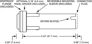
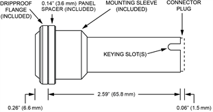
When specified, a sealed body is supplied with a dripproof spacer and dripproof flange that accepts the seal of a sealed cap. Sealed switches do not allow leakage of water through the seal when subjected to the splashproof, watertight, and dripproof sealing test defined in MIL-PRF-22885F paragraph 4.7.20.1 - .3 and MIL-STD-108. Sealed switches also meet the sand and dust test defined in MIL-PRF-22885F paragraph 4.7.26.
Configurations (Switches and NEXSYS Components)
VIVISUN® High Capacity bodies have four available “positions” to accommodate electromechanical switch poles and NEXSYS® components. Positions are identified on the exterior of the switch body and the connector plug as Poles H, J, K, and L. Electromechanical switches each occupy a single pole. NEXSYS Series A components can each occupy a single pole position. NEXSYS Series C components and Series N components can occupy poles J and K simultaneously and NEXSYS Series R components occupy poles J, K and L simultaneously. As shown in Figure 2.1.2-B, there are 23 possible build configurations that reflect the possible arrangements of switches and NEXSYS components. The assignment of selected components to specific pole positions is done at the time of final part configuration. An “open” spacer will be placed in any unused pole position.
| No Switch Poles (Indicator) |
1 Switch Pole |
2 Switch Poles |
3 Switch Poles |
4 Switch Poles | |
|
No NEXSYS
|

|
||||
| Series A only components |

|

|

|

|
|
| Series C components |

|

|

|
||
| Series N components |

|

|

|
||
| Series R components |

|

|
|||
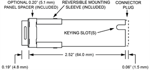
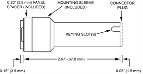
High Capacity bodies without NEXSYS components (only electromechanical switches) have two keying slots and use connector plug (P/N 18-240) for wiring termination. High Capacity bodies with one or more NEXSYS components have only one keying slot and use a specially-keyed connector plug (P/N 18-440) for wiring termination. See Section 2.4 for complete description of High Capacity body (22 socket) connector plugs.
See Section 3.4 for installation instructions and refer to Appendix B for various mounting options, including the proper usage of the optional mounting spacer provided with Standard Square bodies.